MOST USELESS THING EVER!
Fall 2012
Concept
This is probably the most pointless thing I'll ever make. Hopefully.
The idea behind this project was to truly understand the meaning of futility. It was also a gift for my mechatronics professor, for all the lessons he taught us in futil- I mean debugging.
The most useless thing ever is a box with a toggle switch on top. There are many variants on youtube, but they all perform the same function, in that when the user flips the switch some kind of mechanism actuates to flip the switch "off". The idea is simple, and as you'll see further down, the electronics are surprisingly elegant.
CAD
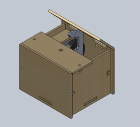
I wanted all the pieces of the box to be 2D patterns that fit together with basic fasteners. That way I could laser-cut all the pieces and assemble the box easily. The screenshot on the left shows an isometric view of the box. The bottom and sides are tabbed to insert together, and the sides are pulled together using screw fasteners. The top-front half is pulled to the sides using the same screw fastening method, and the top-back half is hinged to allow the servo-arm to come up out of the box.
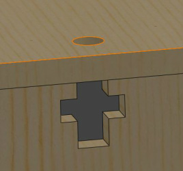
Marlo showed me this little trick for assembling 2D cutouts. A screw is inserted into the through-hole on the top piece and tightened on a nut that is housed in the cross cutout on the mating piece. Extremely simple to design and put together (except when the nut fell into the box while I was inserting the screw... ARGH).
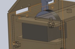
Another neat trick came in handy when I was mounting the servo motor. I used two rectangle cutouts to clamp down on the servo, and attached it to the box using a series of screws, standoffs and nuts. This configuration allowed me to adjust the height and lateral placement of the servo until I had it in the correct position to flip the switch. Much easier than trying to measure everything precisely and having a fixed design.
Electronics
Like I said, the electronics for this project was surprisingly elegant. The elegance comes from the good ol' 555 timer. Wikipedia has a very explanatory image on this useful chip.
Basically, you have a SR latch that gets set when the "TRIGGER" pin falls below 1/3 Vcc (set by an internal voltage divider in the chip) and gets reset when the "THRESHOLD" pin rises above 2/3 Vcc. From the image link, you can see that when the output goes high, it turns on a BJT that connects the "DISCHARGE" pin to ground.
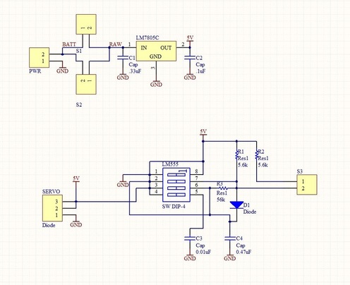
DISCLAIMER: the schematic on the left is all wrong and will fry your 555 if you hook it up that way. For some reason, I don't have the most recent version of the protel files I used, and these are the file before I caught that mistake. Protel was being mischevious and connected all my leads together. Since I no longer have access I can't go back and change the schematic, only view it through their free schematic/pcb viewer. I'll eventually remake it in EAGLE when I get a chance.
Basically, you have a SR latch that gets set when the "TRIGGER" pin falls below 1/3 Vcc (set by an internal voltage divider in the chip) and gets reset when the "THRESHOLD" pin rises above 2/3 Vcc. From the image link, you can see that when the output goes high, it turns on a BJT that connects the "DISCHARGE" pin to ground.
DISCLAIMER: the schematic on the left is all wrong and will fry your 555 if you hook it up that way. For some reason, I don't have the most recent version of the protel files I used, and these are the file before I caught that mistake. Protel was being mischevious and connected all my leads together. Since I no longer have access I can't go back and change the schematic, only view it through their free schematic/pcb viewer. I'll eventually remake it in EAGLE when I get a chance.
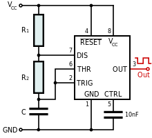 Image from http://en.wikipedia.org/wiki/555_timer#Modes
I used the 555 timer in its "bistable" mode. In this mode, Vcc first acts to charge up capacitor C through R1 and R2. At this point the output goes high and the discharge pin is connected to ground, allowing C to discharge through R2 only. This allows us to have different high and low times (aka PWM).
The rising voltage has a time constant of (R1+R2)*C, whereas the falling voltage has a time constant of R1*C. The math works out such that the time it takes for the capacitor to go from 1/3Vcc to 2/3Vcc is ln(2)*(R1+R2)*C, and the time to discharge is ln(2)*R2*C. Taking 1/(t_high+t_low) gives a frequency of 1/(ln(2) * C * (R1+2R2)). Solving these equations for R1 and R2 (choosing our free variable C to arbitrarily be 0.47uF) and we can have any rise time and frequency that we so desire!
One last trick you can play! By putting the anode of a diode in between R1 and R2 and the cathode between R2 and C, you can essentially bypass R2 on the charging stage. This means the high time depends only on R1 and C (governed by slightly more complex equations, more detail in the wikipedia article). For these equations I used 0.2V for the voltage drop across the Schottky diode.
Backing up a little, servo motors usually like pulses of 1-2ms (1.5ms being neutral) every 20ms. By using the last trick mentioned, I was able to get the 1ms and 2ms high times by having R1 as two identical resistances in parallel for the 2ms high time, and just taking one of them out when I wanted 1ms high time. Since the diode configuration "high time" only depends on R1, dividing R1 in half divides the rise time in half.
Pretty elegant, amirite? The final values ended up being R1 = 2x5.6k in parallel, R2 = 56k, C = .47uF.
Video
| cad_including_bom.zip |
| pcb_protel_dxp.zip |
