LIGHTS LIGHTS LIGHTS
Summer 2013
OVERVIEW
Okay, so here's the first project I'm going to work on after starting this blog. I'd like to make an "LED MODULE" if you will. Picture a block about 1"x1" that houses an RGB LED. Now picture that block in an array of other identical blocks. Now imagine each block knows the state of its neighbors and can light up accordingly. Now imagine all these blocks flickering and dancing in time to MUSIC! Now imagine a WORLD FILLED WITH THESE BLOCKS, DANCING AND SWIRLING AND LIGHTS AND MUSIC, AND THE WHOLE WORLD DANCING AND SWIRLING WITH IT!!! oh yeah!
This is a spawn off a previous project using the arduino LOLSHIELD:
This is a spawn off a previous project using the arduino LOLSHIELD:
The main difference is back then I had no idea what I was doing. Also, I want each light to be a separate, modular, programmable part that can be fit together to make pretty lights. I think Game of Life would still be a cool baseline algorithm to run, but imagine the possibilities of a set of RGB LED's that can respond to music (or any trigger signal really) and light up in whatever pattern you choose!
Software and Algorithms
|
Here's what I got so far:
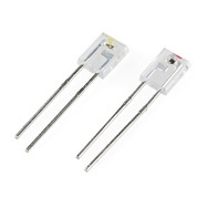
I have a PIC16F690 acting as the module brains. It will take in signals from neighbors and output it's own state to neighbors. I've worked it out such that each block only needs three "ports" per side.
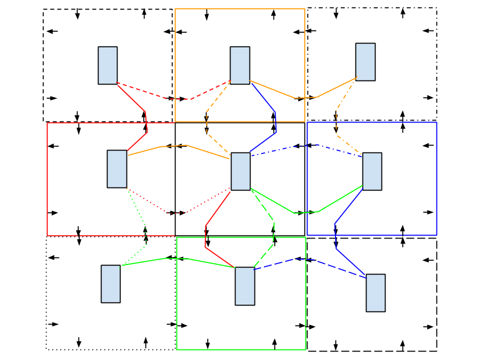
So really that works out to 5 inputs and 4 outputs. The tricky part is that each node has more than 4 neighbors, in fact it has 8! So I had to think a little while on how to get that information to the module. Some ways of tackling this problem: If only we had some kind of pulses, with widths we could modulate... Yep you guessed it! Each cell will get a signal from its neighbor that will consist of 1 of 4 frequencies, which will give it the state of that neighbor and the neighbor CCW to it. Since I couldn't figure out a better way to explain that, check out the diagram to the right. As you can see, each arrow consists of a color and line pattern. The color represents information about the center module's immediate neighbor and the line pattern represents information about the corner neighbors. Thus we are able to get the states of all 8 neighbors with only 4 inputs. To go this route I'd have to get one of these https://www.sparkfun.com/datasheets/Components/General/tlc5940.pdf Since the PIC that I'm using only has 4 output PWM's and I'm already using 3 of them for the LED. I wouldn't be able to use them anyways, as the PIC actually can only output 1 PWM frequency, but route them to 4 separate outputs. Good for the LED, bad for communication. There's gotta be an easier way And there is, have separate connections for each neighbor module. I'm going to try that first. If the spacing doesn't work out I might have to switch back to the aforementioned method. |
Simple transmission of information
|
Hardware
Trying to figure out a good way to physically do the communication between modules. So far, I've been thinking:
- Optical (phototransistor + IR detector) -
- Pros: no contact
- Cons: takes an extra circuit for signal conditioning of the input, sensitive to ambient light
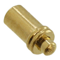
- Electrical - spring probe pin
- Pros: easier, more robust
- Cons: takes up more space, spring force on contact might push modules apart
- For this I'll probably go with a "puzzle piece" design that will hold the modules together. Either that or magnets.
Electronics
I breadboarded up the following two boards:
- PIC16F690 controlling RGB LED, this simulates the modular pieces that would all fit together
- Arduino with BOB-09964 (Breakout Board for Electret Microphone) doing beat detection. Would just need one of these
|
Arduino
PIC16F690 |
| ||||
